I spent pretty much the entire day today bringing WPR’s Rock Springs transmitter back to life.
This transmitter had been off the air since late February. Normally the station runs at 30,000 watts with 12,000 watts of transmitter power output into a 5 bay antenna.
The station had been running at 1,250 watts with a 500 watt backup transmitter since then. The problems all started when the transmitter shut down and filled with snow…I am not sure if the snow caused the shutdown in the first place or if the shutdown allowed the snow to get in (or perhaps a bit of both…)
The problem stemmed from the fact that the transmitter’s exhaust is ducted DIRECTLY to the outside and there was nothing to keep the elements out of the exhaust duct. I generally prefer not to duct transmitters directly to the outside in most cases.
If I do have to duct the exhaust outside I usually put some sort of passive louvers in place as well as a weather hood. The weather hood at this site had apparently fallen off at some point.
I also do not attach the exhaust duct work directly to the transmitter…I generally leave an air gap above the transmitter in case the exhaust path becomes blocked for some reason.
The idea is that if the transmitter DOES shut down the louvers close and nothing gets back into the transmitter. In this case, there were louvers but they were forced in the OPEN position!
No weather hood + dead transmitter + blowing snow + open louvers = one transmitter full of snow!
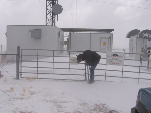
Here are a few pictures from my first visit back in February…
 Plenty of wind and snow outside!
 A tuning stub on top of the transmitter…
Covered in snow! That’s not supposed to happen…
 The tube cavity inside of the transmitter…
Also filled with snow…
I made several attempts to repair the transmitter after this happened but each time I found more problems. The first problem was that the interlocks would not close. That was traced to a failed voltage regulator on the interlock power supply.
Once I resolved the problem with the interlocks, the filament voltage would not come on. The blower would start but the transmitter would not start to warm up the tube. I traced this to a failed opto-isolator chip on the transmitter’s controller.
The third problem was another power supply issue…A rectifier and a capacitor in the grid supply had failed. Once I fixed that problem the transmitter started to work but would not tune up properly. It made some power for a short period of time but quickly failed again.
I dug deeper and found that a number of small ceramic insulators in the tube socket had cracked and would no longer hold the screws in the insulators. These screws were part of a critical tuning circuit which might explain why I could not get the transmitter to tune…
In addition to the cracked ceramic insulators there were other damaged parts in and around the tube socket (bent and missing fingerstock, failed resistors and capacitors, etc). This isn’t exactly the kind of stuff you can find at your local Radio Shack…
I checked on the cost of the parts. The new tube socket was $2000 but I was informed by the vendor that it would not be available until the end of August! I could get one directly from the transmitter manufacturer for about twice that price but instead decided to wait.
The end of August finally came and I placed the order. The new tube socket and other parts arrived a couple of days ago. I had never completely replaced a tube socket before so this was going to be an adventure…
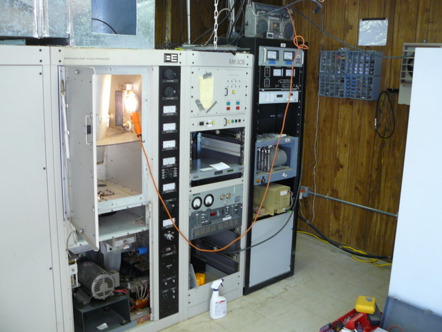
I spent the first half of the day just cleaning up the site and getting rid of clutter so I had a clean area to work.


Once I had the site clean I went to work on the transmitter. It took a lot less time than I thought it would. I had to make some minor modifications to the mounts on the new tube socket but it all worked out just fine. I also replaced the failed resistor and capacitors while I was at it.

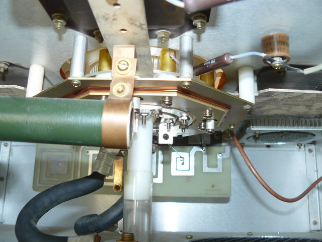
 The underside of the tube socket…Lots going on here!
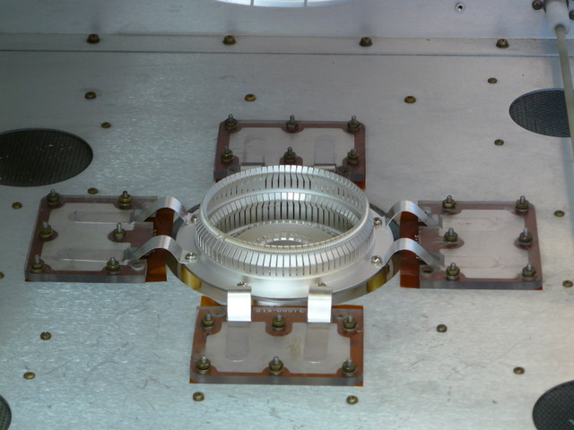
 One shiny new tube socket (with replacement capacitors around the edges) all ready to go!
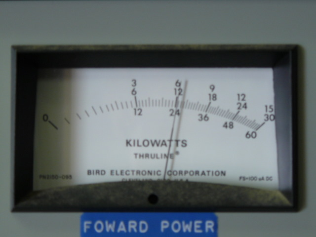
Once I put everything back together I powered the beast up…IT LIVES! No arcs and sparks just 12,000 watts of beautiful RF! I didn’t even have to spend much time tuning it up.
I have become less daunted by the high voltages inside of these rigs over the years but I still take appropriate precautions. I also still hesitate just a bit when I turn on the high voltage, especially after a major repair like this…If things aren’t working properly these boxes can produce a spectacular BANG! This particular box uses 9000 volts across the plate of the tube at around 2 amps.
 All buttoned up and ready to go…

It gives me a great feeling of satisfaction to have tried something like this for the first time and to have it come out successfully.
No user commented in " Bringing a transmitter back to life "
Follow-up comment rss or Leave a