I had brought the transmitter’s controller back to Laramie for some additional troubleshooting. Testing revealed that the issue was not in the controller. I spent some time looking at the schematics for the transmitter and had a theory…There was one other place where the issue could be occurring now that I had ruled out problems with the controller itself. The blower would not start. If the blower doesn’t start, nothing else on the transmitter will power up. One thing after the controller that could prevent the blower from starting is the 3 phase voltage monitor. This device ensures that power is present on all 3 phases of the incoming power feed and that the rotation is correct. If these conditions are not met, SEVERE damage to the transmitter can occur.
I had checked this component earlier but apparently missed something. Once I found the blown main fuse I did not think to revisit the voltage monitor to check if it was now seeing all 3 legs of power. The schematic diagram revealed three fuses in line with the samples to the voltage monitor. Apparently two of those three fuses were blown in addition to the fuse in the main disconnect!
 At the site in my trusty white chariot, UW88 (freshly back from an oil change)
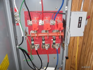 A 400 amp disconnect for the main transmitter…Testing revealed that the 3rd fuse had blown. This is a “wild leg” configuration which can cause numerous issues. More on that later…
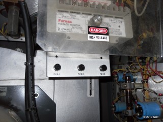 3 phase voltage monitor and fuses for the voltage samples…
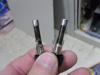 Two of the three fuses feeding the voltage monitor are very much blown…Apparently we took a major hit on the power line. These fuses are normally clear glass.
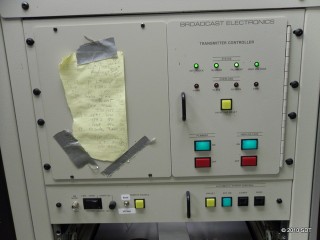 Success! Green lights indicate all is well.
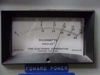 Aaaaaahhhhhh…..17.5 kW of beautiful RF!
 Your tireless engineer enjoys a brief moment of success!
So what caused this? This particular site has a power feed configuration known as “open delta”. This is where two transformers are used for 3 phase power instead of three. Unfortunately this configuration has numerous issues, particularly with broadcast sites. The biggest issue is that one of the 3 phases is a much higher voltage (or a “wild leg”) when referenced to ground. Normally the voltage is 120 between ground and any of the three legs but the voltage on a wild leg can vary drastically and typically is closer to 200 volts. If a site is wired without taking this into account, loads expecting 120 volts can be severely damaged. In addition, this configuration is more prone to issues from lightning and power surges.
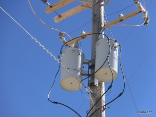 The power feed to KUWZ…Only two transformers on the pole…
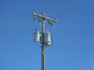 A “proper” 3 phase transformer configuration, further up the road servicing another broadcast site. I have no idea why our site was not wired using this method instead.
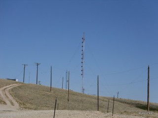 Another FM site further up the road…This is the one served by the transformer bank in the previous picture…
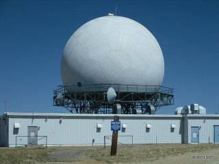 Aspen Mountain is also home to an FAA radar site. At one point in time the site was manned but it is now remotely monitored. The sign warns of excessive RF exposure past that point due to the signal from the radar.
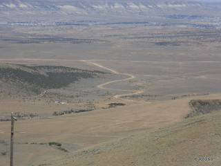 The access road winds down the side of the mountain…Time to get back to the hotel and monitor things for the evening…
No user commented in " More work in Rock Springs… "
Follow-up comment rss or Leave a