Earlier this week we suffered a power failure at our Rawlins transmitter site. The power was ultimately restored but unfortunately our transmitter failed to return to service. Time to mount up on snow vehicles and take a trip to the site to see what is wrong…
Another engineer from the area was able to reach the site and inform me that the exciter appeared to be dead. The only indication was an “Overload” LED. No other indications were lit. Great. This sounds like a power supply issue. The transmitter was happily running but showing “Drive” and “Power Lock” faults indicating that it (as expected in this case) was not seeing any signal from the exciter. This exciter is a bit “unique” but fortunately we had an identical unit at the shop. It had other issues (extremely spurious output) but hopefully we could make one working unit between the two of them.
 After a long ride up to the site on snow vehicles, we finally made it.
Four of us had gone into the site with two snowmobiles and an ATV with tracks…
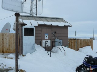 Our site…Look at the huge snow drifts!
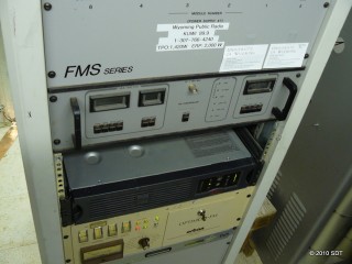 As suspected, the issue appears to be a dead exciter.
The exciter is removed from the transmitter for service…
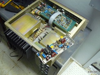 A fuse has blown on the power supply board. Replacing the fuse would likely just result in the new fuse blowing so I decided to swap power supplies between exciters. This board will require further troubleshooting back at the shop.
 Reid begins to remove the power supply board from the other exciter we brought to the site…
 Uh oh…The power supply board in this exciter appears to have a slight modification or field repair. The existing exciter did not have this so it will simply be removed for now.
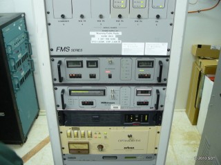 Repairs are complete and the exciter has been reinstalled. Unfortunately the transmitter would STILL not come up. Now what? The transmitter controller was still showing a “Power Lock” fault. This indicates that the APC circuit is not working properly. A quick look at the manual revealed that there are several ways around this. I was able to bypass the offending portion of the APC circuit by changing a jumper inside the transmitter controller to put it in “preset” mode. This mode controls the power setpoint with a potentiometer inside the controller rather than the front panel controls. This means that the front panel and remote power trim controls will no longer function but at least the power level should stay consistent in this mode.
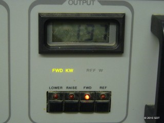 Back on the air at 1.37 kW of output…Normal output is 1.42 kW so this is fairly close. The potentiometer is only a single turn control and very finicky to set. It should probably be replaced with a 10 turn potentiometer to allow finer control in this “emergency” operational mode. While remote power control is no longer possible I can still turn the transmitter on and off remotely as well as monitor the power output.
 I loaded up the tracked four wheeler and prepared to leave the site. Fun stuff!
No user commented in " Repairs in Rawlins "
Follow-up comment rss or Leave a