I have spent the last week working on the tower and antenna for my newest station, 90.7 KUWV. The crew has made tremendous progress but there is still work to be done. My goal by the end of the day would be to have the antenna complete and line hung so that I can test the antenna and start broadcasting a signal for test.
 The crew prepares to send the last two antenna bays up the tower…
 The tower stands tall on this bright sunny day…145 feet and 6 of 8 antenna bays complete. We’ve had great weather for most the week…Quite unusual for January in Wyoming!
 The crew has gone up the tower and begins preparations to mount the final two antenna bays…
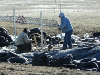 Finishing the rigging on the final two antenna bays…Almost ready to hoist them up!
Attaching the interbay line to the bottom of bay 6 of 8…These bays are spaced 10 feet apart and each is joined by rigid 1 5/8″ transmission line…That’s 80 feet worth of antenna! The entire array was carefully designed as a system at the factory. Each piece must fit into its proper place…
 Bays 7 and 8 on the way up the tower…
 Attaching the final two bays to the tower…
 Connecting the interbay line and bolting the antenna bay to the tower…
 Climbers at the top of bay 5 and bottom of bay 8…Next step, attach the anti-rotation brackets to the bays.
 One of the climbers prepares to attach the anti-rotation bracket to bay 1…These brackets will keep the antenna from moving around in the high Wyoming winds…
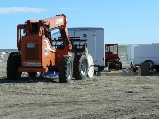 The forklift is used for one final time to move the large spool of transmission line into position…
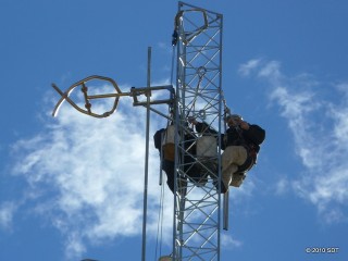 Installation of the anti-rotation bracket on bay 1 is complete…Note the additional angled piece of metal between the antenna mounting bracket and the tower…Supports to protect the inter-bay line will be installed simultaneously as the climbers work their way down the antenna.
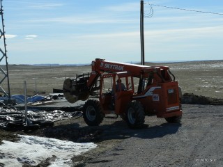 The forklift moves the spool of transmission line into place…
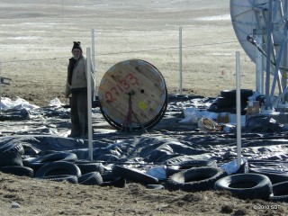 The line is placed on a pair of jackstands to support it while it is being hung on the tower.
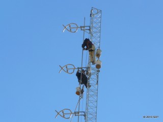 Continuing installation of anti-rotation brackets and inter-bay line supports…The top climber installs the first of many inter-bay line supports (securing the inter-bay lines to the tower) while the lower climber continues installing the anti-rotation brackets.
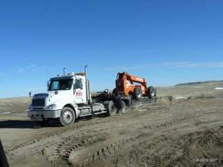 The forklift is loaded up and headed back to RSC in Scottsbluff, Nebraska…Quite a useful tool on this job!
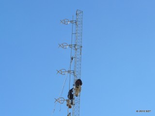 Work on installation of the anti-rotation brackets and inter-bay line supports continues…Almost half way done now!
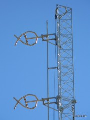 Installation of anti-rotation brackets and inter-bay line support on bays 1 and 2 complete…
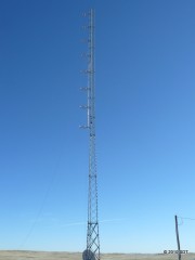 The installation of the antenna is complete and my tower stands proud against the clear Wyoming sky.
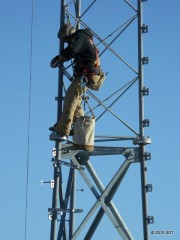 Next step: Mount the brackets on the tower that will secure the feedline as it runs to the antenna.
 Hoisting the transmission line up the tower…
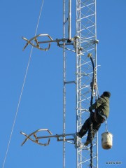 The transmission line is ready to be attached to the feed point of the antenna…
 Attaching the transmission line to the antenna…We’re almost ready to put a signal on the air now!
 Installation complete! The transmission line snakes its way up the tower to the middle of the antenna…
 A gorgeous sunset to end the day…Not quite done yet though…I’m about to put a signal on the air!
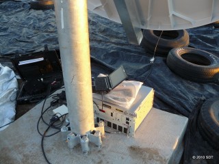 Equipment is temporarily placed near the tower base to test the system…
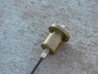
This antenna system uses large 1 5/8″ coax while the test equipment uses much smaller line. An adaptor will be used to bridge the gap…
 A small “netbook” PC is used to operate the test equipment and display results.
 This device is called a PowerAIM 150. It performs many of the functions of a much more expensive piece of equipment at a fraction of the price. This will verify the performance of the antenna system before I connect my test transmitter. A USB to serial adaptor connects this device to the netbook.
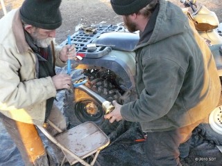 Finishing installation of the 1 5/8″ connector on the transmission line…
 Success! It’s a bit hard to see from this picture but this is a sweep of the antenna system from 88-108 mHz (the entire range of FM broadcast frequencies). You can see the dips in the red and blue lines on the left that indicate good performance from 88-92 with the dip centered at 90.7 where this station will be operating.
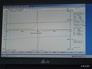 Another sweep of the line…This one is centered at our operating frequency. The large spike in the middle tells me the system is resonant at that frequency. Everything looks good. I connected my ‘test’ transmitter and did some driving. Performance is pretty much as expected. I’m quite pleased.

No user commented in " Lingle tower construction: Day 5 "
Follow-up comment rss or Leave a